Visio 2010 is a great tool for designing PERT charts. Since it lacks some of the shapes needed to easily add and connect nodes with other PERT items, I came up with a few tools to make it easier.
My step-by-step tutorial explains how to create nodes and connections that work seamlessly. After completing these steps, you will have three new shapes to work with:
PERT Node, PERT Connector, and PERT Task.
Step 1: Copy the PERT 1 Shape to a New File
The first problem to overcome is the inability to draw just one line between nodes with a task box glued to the line. To make that happen, the task box needs to be improved. It can be done with a minimum of clicks by following this sequence:
Create a new diagram from the PERT Chart template. Screen shots are included to help you find that.
In the shapes panel on the left side, click on More Shapes, then click New Stencil (US units).
To give the new stencil a name, right click on its title bar and select Save As. In the example, I named it My Custom PERT Shapes.
Now, switch back to the PERT Chart Shapes stencil by clicking its name in the list of stencils.
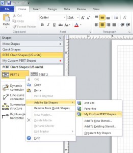
Finally, right-click on the shape named PERT 1. Select Add to My Shapes, then find the name of your new stencil to create the shape copy.
Step 2: Edit the Shape
Now that the desired shape has been copied to a new file, the necessary changes can be made.
Switch back to your new stencil by clicking its title in the list of stencils.
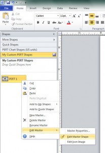
Open the shape for editing by right-clicking it, selecting Edit Master, and then Edit Master Shape.
Look for the Connection Point tool on the toolbar. Just below the Pointer Tool and to the right of the Connector tool, there is an icon with an X on it. That is the Connection Point tool.
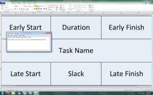
By holding down the Ctrl key on the keyboard, you should get the mouse cursor to change so that it has a little + symbol next to it. This means you will be adding a connection point.
With the Ctrl key held down, click once in the middle of the shape to select it.
Keep the Ctrl key down and look at the rulers at the top and the left side. You should see the position of your mouse cursor being tracked along the rulers. Find the exact center of the shape and click there. You should see a tiny red X appear on the shape.
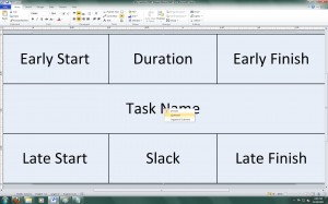
Because this particular connection point will not be used to attach things to it, but rather to attach the PERT task box to other things, the connection point direction must be specified.
Right-click on the little red X and select Outward.
Editing is complete. Close the shape editing window. It will ask you to Update ‘PERT 1’? Just click Yes.
Step 3: Rename the Shape
This part is easier. Simply right click on your shape and select Rename Master. In this example, I named it PERT Task.
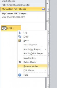
Step 4: Draw a Circle
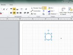
The second problem is the lack of a suitable node shape. Start creating this shape simply by finding the Ellipse tool in the menu next to the Pointer Tool.
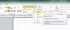
Use this tool to draw a circle exactly ½” across.
By double-clicking on the new circle, you can then give the node a default label such as AB.
When your circle is ready, save it as a shape by dragging the circle off of the diagram and onto your new stencil near the PERT Task shape.
Step 5: Edit the Shape
You will need to open the shape for editing. Again, right-click this shape, select Edit Master, and then Edit Master Shape.

Choose the Connection Point tool, hold down the Ctrl key, and place a connection point at the center of the circle. Follow the same sequence as in Step 2.
The Connection Point is set to Inward by default, so do not change it for this shape.
Close the shape editing window and click Yes to update the shape.
Rename this shape by right-clicking and selecting Rename Master, as in Step 3. For this example, I named this shape PERT Node.
Step 6: Draw a Line
The third problem is a lack of a connector that will snap nicely to the edge of a circle and accept a task box at the middle of the line. Start creating this shape by finding the Line tool in the menu next to the Pointer Tool.
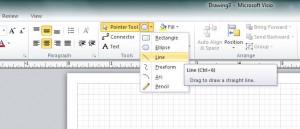
Simply draw a diagonal line, perhaps 2″ long.
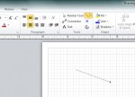
As with the circle drawn earlier, this line should be dragged off of the diagram and onto the stencil near the other two shapes.
Step 7: Edit the Shape
You will need to open the shape for editing. Again, right-click this shape, select Edit Master, and then Edit Master Shape.
This time, a more advanced type of editing is required.
At the top of the ribbon where the tabs appear (such as Home), look for a tab named Developer. Most likely it is not displayed. To turn it on, right click on that area and select Customize the Ribbon. A list of tabs is displayed in the right pane of the dialog box that appears. Click the check box next to Developer so that it is checked and then click OK.
There is no need to click on the Developer tab now, but it must be enabled in order to proceed.
Right click on the line that you are editing. The first option that appears is Show ShapeSheet. Select that option.
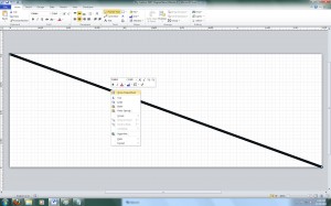
The result may be overwhelming at first. You should get three windows as shown below. The top window is the shape you are editing. The bottom window is the diagram that was open in the background. Ignore both of those for now. The ShapeSheet is the window in the middle.
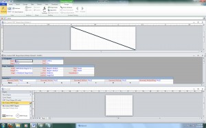
The ShapeSheet is divided into several sections. Scroll to the section named Geometry 1.
The second row of the Geometry 1 section is named LineTo. Double-click the cell in the X column and change its value to =Width-0.25 This will cause the arrowhead on the connector to be spaced away from the end of the line by ¼” inch or the radius of the Node shape. That way, when this line is connected to the center of the Node, the arrowhead will appear at the edge of the Node instead of at the center.
Scroll to the section named Line Format.
Since the line doesn’t actually have an arrowhead yet, double-click the EndArrow cell and change its value to 4. This will add the arrowhead.
Next, it is necessary to edit a section that is not yet listed. Right-click the ShapeSheet area and select the Insert Section option.
Click the check box next to Connection points and then click OK.
Now you can scroll to the Connection Points section.
Double click the cell in the X column and set its value to =Width*0.5 This will create an Inward connection point exactly halfway along the connector line between the nodes.

Close the shape editing window and click Yes to update the shape.
Rename this shape by right-clicking and selecting Rename Master, as in Step 3. For this example, I named this shape PERT Connector.
Step 8: Using the Shapes
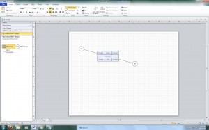
To create a PERT chart, there is a simple but important workflow for using the three new shapes.
- Drag the PERT Node shape to the diagram two or more times.
- Drag the PERT Connector shape to the diagram and connect it to two of the nodes.
- Click the Send to Back button. This prevents the connector from overlapping the nodes.
- Drag the PERT Task shape to the diagram and connect it to the center of the connector line.
You should notice that as you move the nodes, all of the shapes stay connected!
If you move the task box, it will disconnect from the connector line.
If you move the connector line, it will disconnect from the nodes, but the task box will stay connected and move with it.
What the PERT Connector Can Do
The new connector shape is great for connecting nodes with a single straight line. It can also be used to connect the middle of the task box to a node to represent one half of the task line.
What the PERT Connector Can Not Do
Unfortunately, this handy straight line does not make right-angle connections or line hops like a regular connector will. You can still use a regular connector with the nodes to get that behavior. Just be careful as you mix different connectors that they have the same line weight setting. Note in the Line Format editing above, the PERT Connector has a default LineWeight of 0.75 pt, which does not match the default for normal connectors. Also, the default connector does not attach easily to a PERT Node. The best workaround I could find was to enable the snap to shape geometry option.
Automatic Send to Back
I found it a bit tedious to click the Send to Back button for each PERT Connector while creating a PERT chart. I came up with a way to do it automatically, but the process of enabling that is so involved that it would easily fill up a separate tutorial like this one. Just rest assured that it can be done!
With this new tool set, you can create a PERT chart with nodes much faster and with a significantly more professional appearance.


